ENGINE BEARINGS
The backs of the upper case bearings do not have contact with the
holes or seat in crankcase. This poor contact is probably due
to a distorted half bushing, or to a bushing having a different
curvature from the curvature of bearing seat in case.
Either condition would manifest itself only after the bearings
had been subjected to the pounding action of the pistons through
a period of usage. The result would be that one of the upper halves
would be higher than the others. This condition would leave a portion
of the shaft unsupported.
The second is an effect rather than a cause, and occurs when the
crankshaft bearings are adjusted from below, when one or more upper
bushings are out of alignment.
Tightening the bearing cap when the shaft is unsupported, due to
misalignment of the upper halves, will spring the crankshaft. This
is a point that can-not be too greatly emphasized, because the
indiscriminate tightening of the bearing caps has been productive
of more than one case of bearing trouble and timing-gear noise.
Before adjusting the crankshaft bearings of any engine, the shaft
should be tested for alignment and contact, as described later.
A clearer picture of the necessity of alignment of the upper bearing
half can be gotten if the reader will turn to Fig. 14.
The layout is intended to represent a typical five bearing crankshaft,
with No. 4 main upper half bearing out of alignment vertically.
The second, third, fourth, and fifth horizontal columns show the
effects of adjustments when that condition exists, and attention
is called to the effect produced in the fourth column.
ALL BEAR1NGS FITTED AND ALIGNED
Fig. 14. The view at 4 shows how tightening the cap of a bearing
that is misaligned will spring the crankshaft. To prevent any chance
of damage to the crankshaft, the test as shown in Fig. 21 should
be applied to the shaft before any of the caps are tightened. The
center bearing on a three-bearing crankshaft is often pounded out
because of misalignment of the upper half bearing.
It is the impression among a few that the upper half crankshaft bearings are
not called on to providesupport to the crankshaft, to such a degree as the lower
halves. Calibration of the amount of wear on the upper side of the connecting
rod crankpin and the upper main bearing halves showed that in some cases the
load on the upper bearings of both connecting rod and crankshaft was in excess
of the power impulse load on the lower halves.
Longitudinal Misalignment
Misalignment, at the time of overhauling can also arise from bearings
that have been so fitted that their center line is not longitudinally
parallel to the center line of the crankcase drawn from front
to rear of engine.
Besides the effect on the bearings, a crankshaft installed in this
manner will often affect the working of the clutch. Especially
is this true if the engine is part of a unit power plant, because
the bell housing to which the clutch and transmission are fastened
will be out of alignment with the engine flywheel.
A simple test that can be applied without any unusual equipment
consists in mounting a suitable pointer or dial indicator to an
arm which in turn is fastened rigidly to the crankshaft flange.
A view of this test, which is self-explanatory, can be seen by
reference to Fig. 15. The limit of variation on an 8" radius
measured at (A) should not exceed .012".
Fig. 15. The conditions as shown are greatly exaggerated in order
to show graphically what is meant by longitudinal misalignment.
Improper mesh of front end gears and a noisy or binding clutch
will result from a set of bearings thus fitted see (A).
If the dial indicator or a feeler gauge, inserted between pointer
and machined surface of the crankcase, indicates more than .012,
the crankshaft flange should be checked to see that it is square
with the journals. In case the flange tests satisfactorily, the
trouble is due to misalignment of the bearings, which must be replaced
and new ones fitted.
When an engine knock has been traced to one main bearing that is
loose, the cap on that bearing should not be tightened until determination
has been made to see if the upper half bearing is in alignment.
This can be done by cleaning the journal of all oil and dirt and
applying a coat of lamp black or Prussian blue, as explained on
page 7S6. (See also Fig. 23.)
Testing for Circularity
In the matter of alignment and circularity the crankshaft is the
first item of bearing layout to be considered. This holds true
regardless of whether it is intended to adjust the bearings only,
or to renew and refit them. Circularity of crankshaft journals
and crankpins can be tested with a micrometer as in Fig. 16.
The concentricity of the bearing with respect to its journal is
tested by "spotting-in" with Prussian blue, as shown
in Fig. 23.
MAINTENANCE OF CONNECTING-ROD LOWER BEARINGS
The maintenance of connecting-rod lower bearings will be treated
under this heading.
Preparing for the job. If the tests outlined on page 1315 show
that one or more connecting rods are loose enough to require adjustment,
themechanic should prepare for the job in the following manner:
With a hoist or other suitable device raise the front end of the
car so that the bottoms of the front tires are at least three feet
from the floor.
Previous page 1927
Supplement Home Next page 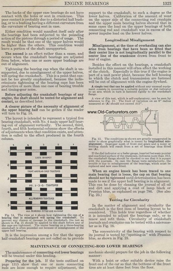
|