Bearings & Rods
Now secure a sliding cot, a quantity of clean rags, hammer, extension
light, pair of side-cutting pliers, and an assortment of end
and socket wrenches to fit the bearings and nuts that are to
be worked on.
When all the tools have been gathered and the car placed in the
position as indicated the mechanic is ready for the job.
Checking Connecting-Rod Trueness
After preparing for the job as outlined above, the oil is drained,
the pan dropped, and the loose rods marked, both on the cap and
shank for identification.
This is done before removing the rods, it being important to insure
that the rod be reinstalled in the same relative position.
The marks made on the rod should face either toward or away from
the camshaft, and this fact should be remembered by the mechanic
as his guide when reinstalling.
Before the rod assembly is removed, however, the mechanic should
turn the crankshaft slowly while seated below and watch the action
of the top of each connecting rod during a full revolution of the
shaft.
If the top of any rod moves back and forth between the piston bosses
more than 1/16", it indicates a bent connecting rod or a piston
pin that is not parallel with the crankpin. Each of the four, six,
or eight connecting rods should be observed in this manner and
correction made either by straightening the rod, installing new
pistons, or reconditioning the crankshaft before the job is sent
out.
With the rod assemblies removed, the mechanic can now proceed to
check the condition of the crank-pins, which will be accomplished
either with a special outside reading dial gauge or with a pair
of outside mikes.
Fig. 16A
Fig. 16. Checking the crankpin with a precision tool is first step
in bearing maintenance. The micrometer (above) and an outside dial
gauge (Fig. 16A) are the only instruments that will accurately
test connecting-rod crankpin for circularity.
Fig. 16A. Ames crankshaft gauge. Will show if crankshaft or crankpins
are out of round, and will measure exact diameters.
This check on the crankpins is to determine if they are tapered,
out of round, or roughened.
The micrometer should be applied to at least three points along
the length of the crankpin to check for taper and at least four
points around the pin to check for roundness or circularity.
When applying the micrometer to different points of the circumference
in the test for roundness, it is also well meanwhile to move the
micrometer from one end of the pin or journal to the other, not,
how-ever, with the idea of testing for both roundness andtaper
in one operation. These two tests should be made separately, as
indicated at Fig. 16.
If the outside type of dial gunge, as illustrated in Fig. 16A,
is used, it will give a continuous reading and will indicate taper
and out of round while being moved around the crankpin.
If either the special outside reading dial gauge or the micrometer
shows that any of the pins are more than 003" out of round,
or if the pin surface is scored or badly cut, it will be necessary
to recondition before attempting to readjust or refit the rod bearings.
Crankpins should have a flawlessly smooth finish.
The best job of reconditioning will be accomplished by mounting
the shaft in a crankshaft grinding machine, but where it is not
advisable to remove the shaft, the mechanic can avail himself of
the several makes of retruing tools, practically all of which can
be used without removing the shaft from the engine.
Where the shaft is roughened slightly and not out of round beyond
.001", it is possible to bring it back to standard surface
by using a lapping tool, such as the one shown at Fig. 8.
Another method often used by mechanics consists in utilizing a
strip of emery cloth wrapped around the crankpin and rotated by
a shoe string of cloth or leather looped once around it. The emery
cloth should be used dry for the roughing work and with oil to
impart a final smooth finish.
The lapping tool also can be used effectively to finish up the
job that was started with the retruing cutter.
In other words, the lapping tool or the emery cloth methods are
excellent for imparting the final smoothness after taper and out-of-roundness
have been removed with the retruing tool.
When the lapping tool is used, abrasive action is secured by turning
the crankshaft while the tool is clamped over the journal from
below.
If either emery cloth or the lapping tool with compound is used,
the pin and adjacent parts of the shaft should be carefully washed
after the reconditioning has been accomplished.
Removable Type Bearings
Assuming now that the crankpins have been inspected and reconditioned
and meet the standards previously mentioned, the mechanic can
then proceed to check the condition of the connecting rod, bearing
surfaces, and cap.
On the majority of engines this inspection can be made in a short
time, as there are few parts that can become deranged in the cast-in
type of rod bearings as now used.
On some constructions it will be found that shims are used, while
in others the bearing is of the style known as the full-round shimless
type.
Regardless of the construction, the first check is to inspect the
condition of the split edges between the rod and cap forgings as
shown at Fig. 17.
Fig. 17. The cap and rod forgings at split faces should be flat
and true.
Previous page 1927
Supplement Home Next page 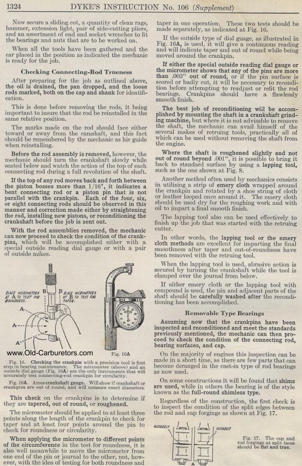
|