Skip to: site menu | section menu | main content
1935 Chevy FRAME AND SPRINGS
Frame
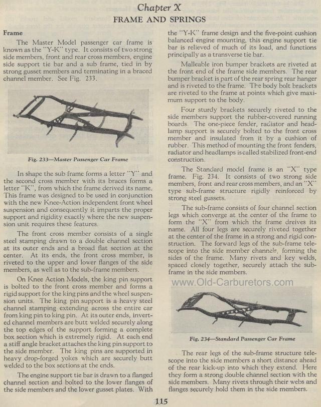
The Master Model passenger car frame is known as the "Y-K" type.
It consists of two strong side members, front and rear cross members,
engine side support tie bar and a sub frame, tied in by strong
gusset members and terminating in a braced channel member. See
Fig. 233.
Fig. 233— Master Passenger Car Frame
In shape the sub frame forms a letter "Y" and the second
cross member with its braces forms a letter "K", from
which the frame derived its name. This frame was designed to be
used in conjunction with the new Knee-Action independent front
wheel suspension and consequently it imparts the proper support
and rigidity exactly where the new suspension unit requires these
features.
The front cross member consists of a single steel stamping drawn
to a double channel section at its outer ends and a broad flat
section at the center. At its ends, the front cross member, is
riveted to the upper and lower flanges of the side members, as
well as to the sub-frame members.
On Knee Action Models, the king pin support is bolted to the front
cross member and forms a rigid support for the king pins and the
wheel suspension units. The king pin support is a heavy steel channel
stamping extending across the entire car from king pin to king
pin. At its outer ends, inverted channel members are butt welded
securely along the top edges of the support forming a complete
box section which is extremely rigid. At each end a stiff angle
bracket attaches the king pin support to the side member. The king
pins are supported in heavy drop-forged yokes which are securely
butt welded to the box sections at the ends.
The engine support tie bar is drawn to a flanged channel section
and bolted to the lower flanges of the side members and the lower
gusset plates. With
115the "Y-K" frame design and the five-point cushion
balanced engine mounting, this engine support tie bar is relieved
of much of its load, and functions principally as a transverse
tie bar.
Malleable iron bumper brackets are riveted at the front end of
the frame side members. The rear bumper bracket is part of the
rear spring rear hanger and is riveted to the frame. The body bolt
brackets are riveted to the frame at points which give maxi-mum
support to the body.
Four sturdy brackets securely riveted to the side members support
the rubber-covered running boards. The one-piece fender, radiator
and head-lamp support is securely bolted to the front cross member
and insulated from it by a cushion of rubber. This method of mounting
the front fenders, radiator and headlamps is called stabilized
front-end construction.
The Standard model frame is an "X" type frame. Fig. 234.
It consists of two strong side members, front and rear cross members,
and an "X" type sub-frame structure rigidly reinforced
by strong steel gussets.
The sub-frame consists of four channel section legs which converge
at the center of the frame to form the "X" from which
the frame dreives its name. All four legs are securely riveted
together at the center of the frame in a strong and rigid construction.
The forward legs of the sub-frame telescope into the side member
channels, forming the sides of the frame. Many rivets and key welds,
spaced closely together, securely attach the sub-frame in the side
members.
Fig. 234— Standard Passenger Car Frame
The rear legs of the sub-frame structure telescope into the side
members a short distance ahead of the rear kick-up into which they
extend. Here they form a strong double channel section with the
side members. Many rivets through their webs and flanges securely
hold them in the side members.