Stewart Vacuum Fuel-Feed System;
Principle of Operation; Care; Maintenance; Adjustments and Installa-
tion. The Autopulse Magnetic Fuel Pump; Principle of Operation
THE STEWART VACUUM GASOLINE FUEL FEED SYSTEM
General Description
The Stewart tank has two separate chambers —the inner or
vacuum chamber (M) and the outer or reserve chamber (N) (see Fig.
1).
The cover and, therefore, the inner chamber has three openings:
1. The fuel inlet (A), which is connected to the main supply tank.
(The fuel passes through the screen S.)
2. The vacuum opening (P), which is connected to the intake manifold
from (J) (as in Fig. 2).
3. The atmospheric opening (K).
The outer or reserve chamber also has three openings.
1. At the top the opening (H) to the atmosphere at all times through
vent tube (K) and atmospheric passage (H).
2. In the bottom, opening (D). This is closed by drain cock or
pipe plug which may be removed for draining or cleaning the tank.
3. Outlet (E) which is connected to the carburetor float bowl.
How It Operates
The pumping action of the pistons in the engine creates a suction
or vacuum in the intake manifold.
By connecting the Stewart tank to the intake manifold, air is withdrawn
from the inner chamber, thus reducing the pressure below that of
the atmosphere. The fuel in the main supply tank being under atmospheric
pressure is forced into the inner
' A good example of an air-pressure gasoline fuel-feed system is
the Cadillac. See Instruction 97, Fig. 1, page 1283.chamber (this
action is commonly called suction) from where it flows to the outer
chamber, as explained later.
As the Stewart tank is always installed at a point higher than
the carburetor, the fuel flows by gravity to the carburetor. Fig.
2 shows the relative position of the Stewart tank and the carburetor.
By means of an arrangement of four levers and two springs, float
(F) in the inner or vacuum chamber (M) operates the vacuum valve
(B) and the atmospheric valve (C).
When the vacuum chamber (M) is empty the float is down, as shown
in Fig. 3, the atmospheric valve (C) is closed and the vacuum valve
(B) is open.
The suction of the intake manifold is applied to the inner chamber
(M) through the vacuum connection and open vacuum valve (B) and
reduces the pressure in inner chamber (M) below that of the atmosphere.
This closes flapper valve (G), as outer chamber (N) is at atmospheric
pressure.
Fuel from the main supply tank is, therefore, forced into inner
chamber (M), through screen (S) and fuel inlet (A), as this also
is at atmospheric pressure.
As inner chamber (M) fills with fuel float (F) rises. As float
(F) reaches the top of its stroke the spring lover is pushed above
pivot (Z) causing the springs to lift the valve lever which closes
vacuum valve (B) and opens atmospheric valve (C), allowing atmospheric
pressure to be established in chamber (M).
As the pressure in both chambers is now equal the fuel flows by
gravity through flapper valve (G) into outer or reserve chamber
(N) allowing the float (F) to drop gradually.
As the float (F) reaches the bottom of its stroke the springs are
pulled below pivot (Z) and the valve lever opens vacuum valve (B)
and closes atmospheric valve (C). The intake manifold vacuum again
lowers the pressure in inner chamber (M), fuel is forced into inner
chamber and the operation is repeated.
This operation is continued at a rapid rate until the fuel level
in chamber (N) comes to a balance with the fuel level in chamber
(M) and operates thereafter as the carburetor demands the fuel.
As the gravity chamber (N) is always open to the atmosphere, through
passage (H) and vent tube (K), a perfect, even flow of fuel to
the carburetor is maintained by gravity.
Previous page 1927
Supplement Home Next page 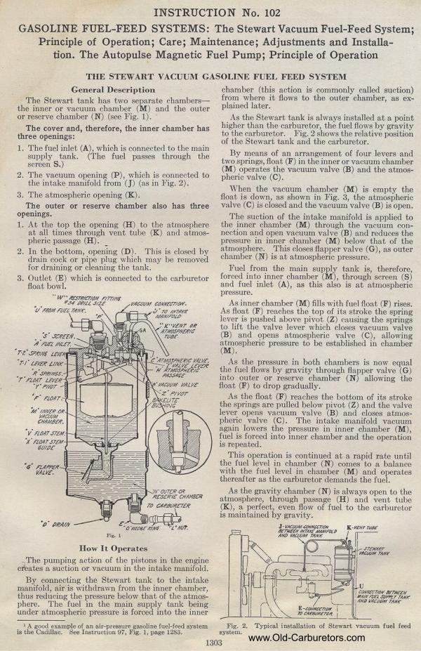
|