CADILLAC CARBURETORS:
Gasoline System. Carburetor Construction;
GASOLINE SYSTEM
The general arrangement of the air-pressure gasoline system is
shown in Fig. 1.
Strainers and Settling Chamber
A strainer is attached to the carburetor at the point where the
gasoline enters. This strainer consists of three gauze discs which
can be removed for cleaning after removing the six screws that
hold the cover. Before doing this the air pressure should be relieved
by removing the gasoline tank filler cap.
In installing the strainer, the two fine mesh screens should be
put in place first with the rolled edges out-ward. The coarse screen
is the last to go in and should have the rolled edge toward the
other discs.
Strainer and settling chamber on frame: Before approximately engine
number 118,000 there is also a settling chamber and strainer in
the gasoline line. This is attached to the left-hand side bar of
the frame under the front floor boards.
To clean this strainer, first relieve the air pressure at the tank
and then unscrew the drain plug. The strainer screen which is attached
to the drain plug may be cleaned by washing it in clean gasoline.
Automatic Pressure Pump
Removal: Disconnect from the pump the air sup-ply pipe leading
to the air pressure relief valve.
Remove the two nuts and lock washers which hold the pump to the
engine, at the same time holding the pump to prevent the spring
from jumping out and being lost.
Inspection: The proper clearance between the piston and cylinder
of the gasoline system pressure pump on the engine is a matter
of special importance.
If this clearance is too great, the piston is likely to pass oil
into the air chamber. If the clearance is too small the pump may
be noisy in operation when cold, resulting from the fact that the
piston is slow to return and the roller does not follow the cam.
It has been determined that a clearance of at least .001" is
necessary to insure quiet operation at all temperatures, and that
a maximum clearance of .0013" should not be exceeded.
As these limits are too fine for measurement in the ordinary manner,
a special method is used to govern the clearance between the piston
and the cylinder.
This method is to turn the pump upside down and measure the time
required for the piston to fall of its own weight. A stop watch,
although desirable, is not necessary for this test.
To make the test, the spring should be removed and all traces of
oil and dirt should be wiped from the cylinder and piston.
Turn the cylinder upside down and insert the piston, holding it
until ready to take time.
Release the piston and start timing at the same instant. The piston
will fall almost instantly to the point at which the inlet port
is closed. Its travel will then be very slow for a distance of
about " or until the outlet port is uncovered, when the piston
will again fall rapidly.
The period during which the piston travels slowly is the period
to be tinned and should be not less than twenty seconds nor more
than forty seconds.
If this period is less than twenty seconds, the clearance between
the piston and cylinder is too great and the pump should be replaced.
If more than forty seconds are required, the piston should he lapped
with ground glass and kerosene, or with Bon Ami and water.
After lapping, all trace of the lapping material should be washed
off and the test should be repeated.
Inspection of check valve: Remove the cap on the check valve and
clean and inspect the valve and its seat.
Hand-Pressure Pump
Removal: Disconnect the air pipe from the pump.
Remove the large hexagonal nut and lock washer on the front face
of the instrument board. The pump may then be removed.
Unscrew the knurled cap from the end of the pump nearest the handle.
Remove the plunger.
Inspection: Examine the leather on the plunger. It should be soft
and pliable.
The barrel of the pump should be wiped out and a few drops of fine
oil placed on the walls.
Examine the check valve and the valve seat.
Air-Pressure Relief Valve
Adjustment: A pressure relief valve is connected in the air line
of the gasoline system for the purpose of preventing excessive
pressure.
Fig. 1. Gasoline system (The settling chamber and strainer shown
in the gasoline line is not used after engine number
118,000; a tee takes the place of them.
Previous page 1927
Supplement Home Next page 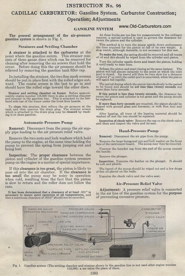
|