MARVEL CARBURETORS:
MARVEL MODEL "T" CARBURETOR USED ON BUICK 1926
AND 1927 SIX CYLINDER CARS
('I'3— Standard Six T4 — Master Six)
The Marvel model "T" carburetors are of the automatic
air-valve, two jet, heat-controlled types.
Construction
The construction embodies a main body or mixing chamber (1, lig.
1), and a conventional float chamber bowl (2), with fuel strainer
(3) attached at point of entrance of fuel to bowl.
Within the mixing chamber are two nozzles which proportion the
amount of gasoline used in the mixture.
Fig. 1. Sectional side view of the model "T" Marvel
carburetor.
Fig. 2. Sectional end view.
One of these nozzles (' ), called the "low speed," is
regulated by the gasoline adjustment needle (5) at bottom of carburetor
and the other (6), called the "high speed," is controlled
by the automatic air valve (7).
An air screw (8) is provided which regulates the pressure of the
air-valve spring (9) enclosed therein.
Within this screw is also enclosed a plunger (10), connected by
a link to the air valve (7).
The function of this plunger is to provide a resistance in addition
to that of the air valve spring to assist in acceleration. This
arrangement of plunger (10) and air valve screw (8) is termed the
dash pot.
A further control of the high-speed jet (6) is provided by the
fuel-metering valve (11, Fig. 2) operated by the carburetor throttle
(12, Fig. 2) through link (13).
This valve provides the maximum fuel feed to the "high-speed" nozzle
(6) when the throttle is fully opened for high speeds and for quick "pick
up."
1 An air cleaner of the AC make is placed on the main air intake
(Fig. 3) of carburetor on the Buick, Nash, and Oakland. The Buick
and Nash carburetors are identical so far as adjusting is concerned,
the only ,change being in casting shape, calibration, and levers.
The Oakland 1926 model Marvel A-2S carburetor is greatly different.
See page 1275.
During the ordinary driving ranges this valve (11) controls the
amount of fuel being used, thus providing all the economy possible.
'i his valve is entirely automatic and requires no adjustment.
A choke button (see top button above J, in Fig. 3, is provided
on the instrument board to assist in starting. It is connected
to (15, Figs. 1 and 2).
Pulling out this button closes a butterfly valve (14, Fig. 2)
the air intake passage of carburetor, which restricts the air
opening of the carburetor, and consequently produces a richer
mixture. This button should be released at once upon starting.
A control lever (J), (see Fig. 3) is also placed on the instrument
board to provide for manual regulation of heat control in addition
to the automatic heat control mechanism of the carburetor.
Heat Control
The carburetor and manifolds have been designed to utilize the
exhaust gases of the engine to insure complete vaporization and
a consequent minimum consumption of fuel.
Fig. 2A. This illustration gives the reader an idea how the main
exhaust can be directed down through the riser and out the tube
by damper control valve (L) and another valve in tube (M) explained
in text.
This is accomplished by the use of a double-walled riser which
carries the throttle placed between the carburetor and the intake
manifold.
This riser is connected to the exhaust manifold in such a manner
that the exhaust gases pass between the walls (W) (Fig. 2) of
the riser, and through the outlet tube (M) (Fig. 1) front riser
to the exhaust pipe.
The amount of heat thus furnished to the riser jacket is controlled
by two valves: one in the exhaust pipe above the outlet tube
from riser and one in the outlet of riser heat jacket.
The valve (A) (Fig. 3), in the exhaust pipe is connected to the
throttle lever of carburetor in such a manner that the greatest
amount of heat is had iu the jackets (W) (Fig. 2) of riser when
the throttle (12) is only partly open, as in idling and at slow
speeds, and a decreasing amount as the throttle is opened further
for higher speeds.
By means of the heat-control lever (J) (Fig. 3) on instrument
board this automatic action of the heat valve may be varied to
suit weather and driving conditions.
The valve (A), (Fig. 3) described above in main exhaust line
at front end of engine, has a shaft which has a slot in the end.
This slot indicates position of
Previous page 1927
Supplement Home Next page 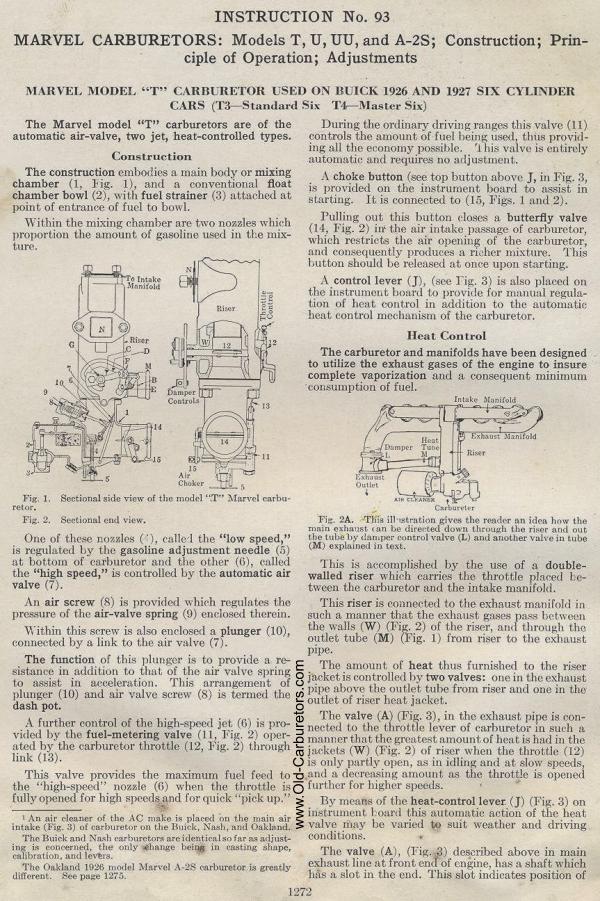
|